This blog post was originally published by Twisthink. It is reprinted here with the permission of Twisthink.
The exciting world of embedded cameras is experiencing rapid growth. Digital-imaging technology is being integrated into a wide range of new products and systems. Embedded cameras are becoming widely adopted in the automotive market, security and surveillance markets, medical market, and industrial systems market. In fact, image sensor sales growth in these markets is predicted to outpace the smartphone and digital camera markets. This is the result of the mass availability of increasingly powerful, low-cost processors and the continued performance enhancement and cost reduction of CMOS image sensors.
Designing an embedded camera can be complex. There are numerous sensor, lens, lighting, and system trade-offs that need to be made to meet the desired application constraints. At Twisthink, we employ “lean” thinking to embedded vision applications by applying mathematical camera models to understand the trades and accelerate the camera design for our clients.
Camera modeling is especially valuable in the early stages of the product design because it allows designers to:
- quickly understand the class of camera required by an application
- easily make appropriate trade-offs with visual relationships between camera design parameters
- rapidly test different lens and image sensor combinations before purchasing and assembling components
Simple equations can be used to model many camera design parameters including image sensor Nyquist limit, hyper-focal distance, horizontal and vertical field of view, depth of field, orthogonal and normal image blur due to motion, magnification, image distance, and image pixel resolution. Parameters that cannot be modeled with simple equations must be simulated or measured with real-world components.
The Thin Lens Model
The thin lens model is the foundation of the camera model. The thin lens model sufficiently models complex lenses when the lenses have little or no distortion. When distortion is introduced, a distortion model can be used as an input to the thin lens model. The coefficients of the distortion model must be measured or provided by the lens designer.
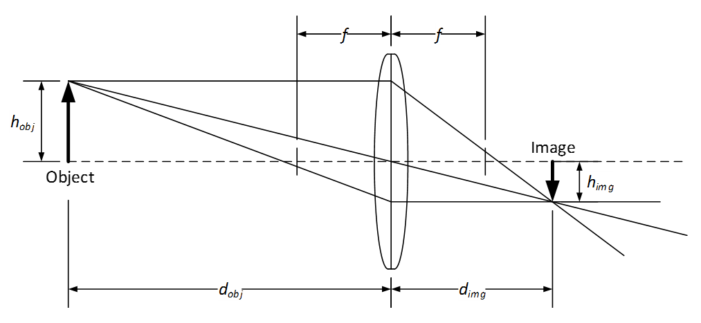
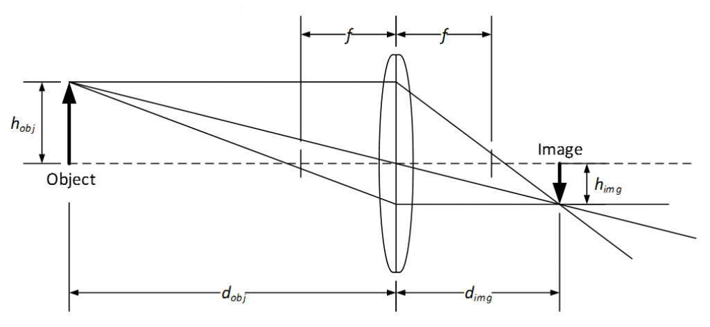
The figure above shows a thin lens ray diagram with an object of height h_obj located at a distance d_obj in front of the lens and an image of height h_img located at distance d_img behind the lens. The lens has focal length f and no distortion. In this case, because the object is beyond the focal length of the lens, the image is on the backside of the lens. Further, because the lens is convex, the image is real (not virtual) and inverted.
The object distance d_obj and the image distance d_img are related to the focal length f using the Gaussian Lens Formula or “lens-makers” formula shown in Eq. 1.

The ratio of the image distance d_img to object distance d_obj defines the magnification m of the lens shown in Eq. 2.

Example: Computing Field of View and Pixel Resolution
The camera’s field of view and pixel resolution are easy to understand camera parameters. We will use these to show how a camera model can accelerate the camera design by allowing the designer to rapidly evaluate a lens and image sensor combination before purchasing it.
Imagine you are asked to specify a camera module for a detection application. You’ve already talked with a few module providers and have a few options that meet the cost target. Before making any purchases, you would like to know if a 1080p camera module with a 6 mm focal length lens will provide an appropriate field of view and pixel resolution. Your application requires a system that can accurately identify a 1 inch wide object placed 10 m in front of the camera. Your detection algorithm requires at least 20 pixels across the object for robust detection.
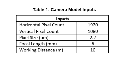
The 1080p camera has 1920 horizontal pixels, 1080 vertical pixels, and a pixel size of 2.2 um by 2.2 um. Let’s assume that the lens is mounted on the image sensor with minimal tilt and is centered on the pixel array. Using Eq. 1 and Eq. 2 as the foundation, the camera module’s field of view and pixel resolution can be evaluated on paper before purchasing the camera module.
The field of view (FOV) of a camera system is the extent of the world that is visible by the camera. Because image sensors are rectangular, the camera field of view is typically specified with a horizontal field of view, a vertical field of view, and/or a diagonal field of view. The field of view of the camera is a function of the lens focal length and the horizontal and vertical dimensions of the image sensor's active pixel array (in a non-distorted system).
(Note: The field of view can be limited by the lens’ image circle if the image circle diameter is less than the diagonal dimension of the image sensor's pixel array. In this case the field of view will be limited by image circle diameter and not the horizontal and vertical dimensions of the image sensor.)
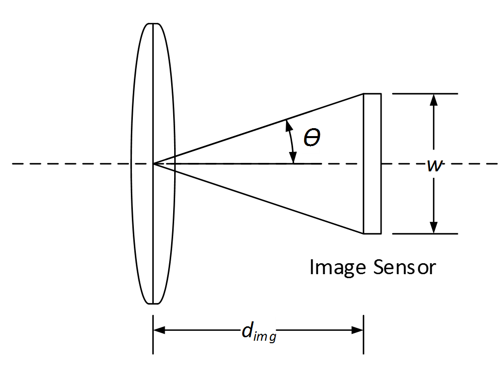
Using the triangle shown above with base equal to the image sensor dimension w and height equal to the image distance d_img (as computed using Eq. 1), the field of view is computed with the following equations:


If the horizontal field of view is being computed, w represents the horizontal dimension of the image sensor's active pixel array and is computed as the pixel size multiplied by the horizontal pixel count. If the vertical field of view is being computed, w represents the vertical dimension of the image sensor's active pixel array and is computed as the pixel size multiplied by the vertical pixel count.
In image processing, an image sensor’s pixel array performs pixel sampling by converting a continuous-spatial signal (the object or scene being viewed) into a discrete-spatial signal or digitized signal (the image of the object). The sampling rate of the image sensor determines the pixel resolution of the digitized image. The sampling rate is a function of the object distance d_obj, the focal length of the lens, and the image sensor's active pixel array pixel count.
For a given object distance d_obj, the image distance d_img can be computed using Eq. 1 and the magnification m can be computed using Eq. 2. The pixel resolution in pixels per inch (ppi) can then be computed using Eq. 5.

Using the camera module specifications described above as inputs (shown in Table 1) and Eq. 1 through Eq. 5, intermediate values and final parameter values can be computed (shown Table 2).
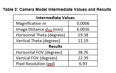
The horizontal and vertical field of view, though defined as angles, define a rectangular working area at 10 m in front of the camera. At this working distance, every one-inch object will be sampled by about 7 image sensor pixels which is below the detection algorithm requirements.
There are two main ways to increase the pixel resolution. The first is to increase the focal length. This increases the pixel resolution but decreases the camera field of view. The second is keep the focal length at 6 mm and decrease the working distance. The camera will have the same field of view but the working area that the camera views will be reduced. Sometimes it is possible to improve pixel resolution by slightly increasing the focal length while increasing the image sensor pixel count with a reduced pixel size. This is the least likely approach because image sensors are available at incremental resolutions and pixel sizes.
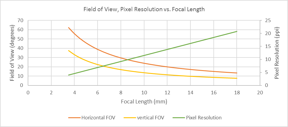
The figure above shows the relationship between focal length and horizontal/vertical field of view and focal length and pixel resolution for a 1080p camera module with a working distance of 10 m. According to this chart, to achieve the required pixel resolution, the focal length would need to be increased to round 18 mm. At this focal length, the field of view is greatly reduced.
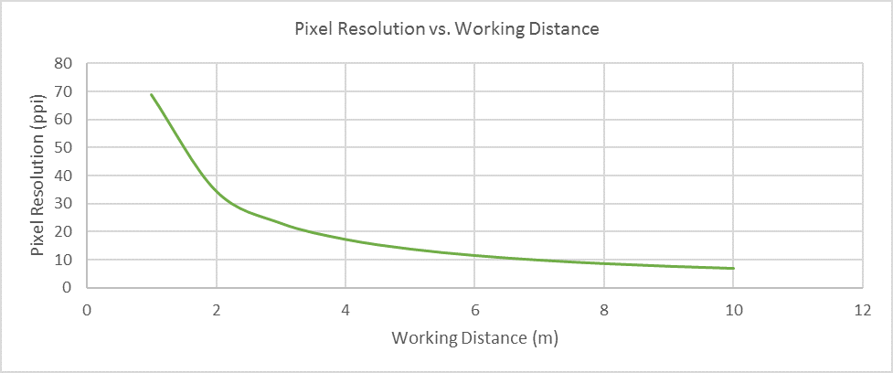
The figure above shows the relationship between pixel resolution and working distance for a lens with focal length of 6 mm and a 1080p camera module. To achieve 20 ppi pixel resolution and use the 1080p camera module, the working distance would need to decrease to less than 4 m.
With the understanding of these parameters and their relationships in-hand, the designer has three options:
- Decrease the working distance
- Find a new camera module
- Work with the algorithm to decrease the pixel resolution requirement
Without a camera model, the designer would have purchased a sample camera module, created a capture tool (if it did not exist), captured images at various working distances, and analyzed the results. These simple computations allowed the designer to bypass these steps and provided insight into the parameter relationships and trade-offs.
Conclusions
As a member of the Embedded Vision Alliance, Twisthink is empowering product creators to incorporate camera systems into new products and applications by applying a human-centered design approach to problem solving alongside deep technical expertise in embedded systems, vision systems, and connectivity. If you are interested in incorporating camera systems into your products and/or services but need support specifying and designing the appropriate camera system, contact us at [email protected] or 616.393.7766.
By Ryan Johnson
Lead Engineer, Twisthink